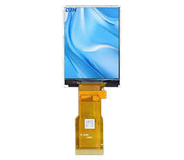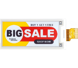
Display module architecture can have a major impact on the size, power consumption, assembly process, and long-term reliability of an electronic product. For compact equipment such as handheld instruments, smart locks, remote controls, medical devices, and portable meters, even a few millimeters of additional display thickness can complicate enclosure design.
A COG LCD, or Chip-on-Glass LCD, addresses this challenge by mounting the driver IC directly onto the LCD glass instead of placing it on a separate printed circuit board. This creates a more compact module structure and can reduce the number of components required around the display.
However, COG technology is not automatically the best choice for every product. Engineers should compare it with conventional PCB-based LCD modules according to mechanical space, power requirements, interface design, production volume, maintenance strategy, and environmental conditions.
The most important difference is where the LCD driver IC is mounted.
In a conventional PCB-based display module, the driver electronics are mounted on a printed circuit board connected to the LCD glass.
A cog lcd display bonds the controller or driver IC directly onto the glass using conductive bonding technology.
This removes the need for a separate PCB dedicated to the display driver.
The simplified structure can include:
LCD glass → driver IC bonded on glass → FPC connection → host PCB.
This architecture is particularly attractive when the product designer wants to minimize:
overall module thickness;
PCB area;
connector count;
component quantity;
display assembly space.
DJN's COG LCD solutions are designed with this compact structure and can use flexible FPC connections to interface with the customer's mainboard.
For small electronic equipment, that structural difference can influence the complete industrial design.
Compact electronics frequently have strict dimensional limits.
A handheld medical instrument, for example, may need to fit the LCD, battery, main PCB, buttons, connectors, and enclosure into a very small body.
Using a separate driver PCB around the display consumes valuable internal volume.
A cog lcd module integrates the driver much closer to the glass itself. DJN's COG products can achieve very thin module structures, making them suitable for applications where mechanical space is limited.
This can benefit products such as:
smart locks;
glucose meters;
handheld measurement instruments;
remote controllers;
portable industrial devices;
compact household electronics.
The thinner display also gives mechanical engineers more flexibility when designing bezels and housings.
However, reducing thickness should not be the only design objective. FPC routing, connector position, mounting pressure, and protective structure still need to be considered during mechanical development.
Many COG displays are used in battery-powered equipment, where power efficiency is important.
Monochrome LCD technologies such as TN, STN, and FSTN generally require less power than full-color TFT displays, especially when the application does not need animation or complex graphics.
Combining these LCD technologies with a compact cog lcd architecture can make the module suitable for low-power electronic products.
BOM simplification can also be an advantage.
Because the driver IC is bonded directly to the glass, the display may require fewer supporting mechanical and PCB components than a traditional module.
Potential benefits include:
reduced PCB size;
fewer connectors;
simplified assembly;
lower module weight;
more compact packaging.
However, cost should be evaluated according to the complete project.
A standard PCB-based module may still be more economical for low-volume projects if an off-the-shelf design already meets the requirement.
COG technology becomes particularly attractive when space, power, and product-specific integration justify a more optimized module structure.
The FPC is one of the most important interfaces in a cog lcd module.
Because there is no traditional display PCB carrying a large connector, the flexible circuit normally links the glass module directly to the host electronics.
This means several factors should be confirmed early:
FPC length;
FPC exit direction;
pin definition;
connector pitch;
bending radius;
host PCB position.
An FPC that exits in the wrong direction can create mechanical problems even when the LCD itself fits perfectly.
For customized products, the FPC arrangement should therefore be reviewed together with the enclosure and mainboard layout.
The module should also be supported correctly.
LCD glass is rigid but relatively fragile. Mechanical pressure should not be concentrated on the bonded IC area or unsupported glass edges.
Engineers should provide drawings of the available display space and mounting structure when requesting a customized cog lcd display.
Portable equipment may experience repeated movement, drops, vibration, and transportation shock.
A compact COG architecture can reduce the number of rigid interconnections between the LCD and separate electronics.
This can be useful in devices where a large display PCB would increase size or introduce additional connection points.
However, reliability still depends on:
glass quality;
IC bonding process;
FPC bonding;
connector design;
enclosure support;
operating temperature;
humidity;
vibration conditions.
For industrial equipment, the display should therefore be evaluated as part of the finished assembly.
A module that works well on a test bench may behave differently after it is mounted into an enclosure exposed to mechanical stress.
Buyers should discuss expected temperature range and mechanical environment before selecting a display.
Prototype validation should include the final FPC routing and enclosure structure rather than testing the LCD separately.
A cog lcd module is particularly attractive when the product requires:
compact dimensions;
low power consumption;
simple monochrome information;
customized segment or dot-matrix layout;
direct FPC connection;
limited PCB space.
Typical applications include portable meters, smart-home controls, electronic locks, medical instruments, remote controls, and industrial handheld devices.
A conventional PCB-based LCD may still be preferable when the application benefits from an integrated board containing buttons, backlight circuitry, connectors, or additional electronics.
The correct decision should therefore be based on complete system architecture.
Before requesting a customized module, buyers should provide:
visible area;
outline dimensions;
display content;
TN/STN/FSTN preference if known;
positive or negative display mode;
backlight requirement;
viewing direction;
operating voltage;
FPC requirements;
operating temperature;
annual volume.
This information allows the display manufacturer to determine whether an existing COG platform can be adapted or whether a new design is required.
COG means Chip-on-Glass. The LCD driver IC is bonded directly onto the glass rather than installed on a separate display PCB.
It often can be because the separate driver PCB is eliminated, allowing a more compact structure.
Yes. Depending on the project, customization can include display pattern, dot matrix, FPC, backlight, viewing direction, dimensions, and interface requirements.
Yes. Monochrome cog lcd solutions are commonly used in low-power portable electronics.
Provide dimensions, display content, interface, FPC direction, backlight, operating voltage, temperature range, viewing direction, and estimated production volume.
A well-designed cog lcd display is not simply a smaller LCD. It is an integrated component whose glass, driver IC, FPC, mainboard, and mechanical structure should be planned together.



 English
 中文
 日本語
 한국어
 français
 Deutsch
 Español
 italiano
 русский
 Türkçe
 português
 Indonesia