A capacitive touch screen detects changes in capacitance when a finger interacts with its sensing surface. A touch controller measures those changes, determines the touch position and sends coordinates to the equipment’s software. Conventional capacitive sensing does not require two conductive layers to be pressed together.
For industrial equipment, understanding this principle helps explain why cover glass, gloves, moisture and the surrounding electronics can influence touch performance. A panel should therefore be evaluated in the conditions in which operators will actually use it.
A capacitive touch screen is an input device that uses an electrically sensitive electrode structure to detect user interaction. In equipment with a display, the touch sensor is positioned over or integrated with the visual interface, allowing an operator to select controls shown on the screen.
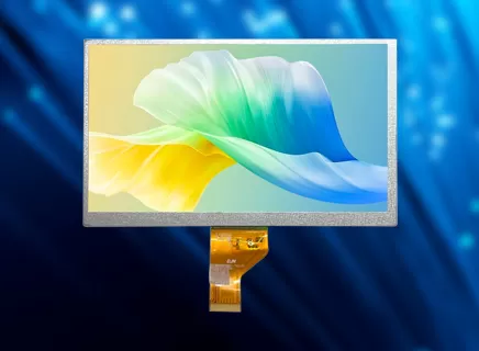
The touch sensor and the display perform different functions. The display creates the image; the sensor detects where the operator interacts with it. An image can appear correctly even when touch communication or coordinate alignment has not been completed.
Projected capacitive technology, often shortened to PCAP, is commonly used for transparent touch interfaces. The sensing arrangement, controller and software determine the supported touch behavior.
DJN’s capacitive touch panel category includes glass-based and film-based construction options. Choosing between them requires consideration of the complete assembly, including the cover, sensor, mounting arrangement and intended operating environment.
Capacitance describes the ability of a system of conductors and insulating materials to store electric charge. A finger interacting with the sensor changes the electrical conditions around the electrodes.
Two important measurement approaches are self-capacitance and mutual capacitance. Texas Instruments’ capacitive sensing basics explains that self-capacitance measures an electrode relative to a reference, while mutual capacitance measures coupling between transmitting and receiving electrodes. A finger affects those measurements differently, so the two approaches should not be treated as identical.
At a system level, touch detection follows a sequence:
Establish a baseline: Record sensor measurements without an intended touch.
Scan the sensing area: Acquire measurements from the relevant electrodes or sensing nodes.
Identify meaningful changes: Separate a potential touch signal from background variation.
Estimate position: Use the spatial distribution of the signal to calculate coordinates.
Report interaction: Send the touch information to the host software.
The host then decides what the touch means. Selecting a button, moving a slider or interpreting a gesture is an application function built on the reported coordinates.
Multi-touch behavior also depends on the supported sensing architecture, controller and software. It should be specified and tested rather than assumed from the word “capacitive.”
A touch assembly contains several elements with different roles. Its exact construction depends on the selected design.
| Assembly element | Main role | What equipment manufacturers should confirm |
|---|---|---|
| Cover lens | Provides the operator-facing surface and mechanical protection | Material, thickness, outline, printing and surface requirements |
| Sensing structure | Carries the electrodes used for touch detection | Sensor construction and active touch area |
| Adhesive or bonding layers | Join selected parts of the assembly | Bonding arrangement and compatibility with the optical design |
| Flex connection and touch controller | Connect and process the sensor signals | Controller identification and the supplied connection arrangement |
| Display module | Presents the visual interface beneath the touch surface | Alignment between the image and active touch region |
G+G generally describes a cover-glass and glass-sensor construction, while G+F+F uses film-based sensing layers beneath the cover glass. These names describe structural approaches; they do not establish universal performance rankings.
For a glass-based construction, DJN’s gg structure page provides model information for reviewing candidate assemblies. Confirm the selected model’s drawings and specifications rather than applying one product’s dimensions to the entire category.
Pay attention to the relationship between the visible display area and the active touch area. Decorative printing, enclosure openings and edge controls all need to be considered together.
A complete layer description is more useful than a broad claim that one construction is always more durable, thinner or more sensitive.
Touch behavior depends on the interaction between the sensor and its surroundings. Conditions that change electrical coupling or introduce unwanted signals deserve attention during evaluation.
A glove adds material between the finger and the sensing electrodes. Its thickness, material and fit can affect the detected signal.
TI’s capacitive touch design guide discusses gloves as an additional dielectric layer and notes the need to account for variation between glove types. Its moisture guidance also explains that liquids can alter capacitive measurements. These principles help frame the questions to test in a touchscreen assembly.
Specify the gloves operators actually wear. A demonstration with one thin glove does not establish compatibility with every protective glove used on a production line.
Water droplets, a wet finger and a continuous surface film are different operating conditions. Define which conditions the equipment must tolerate and what behavior is acceptable during each one.
Enclosure protection against water ingress and correct touch operation on a wet surface are separate requirements. Neither should be used as a substitute for evidence of the other.
Cover thickness, sensor geometry and nearby components can influence the touch signal. Infineon’s industrial capacitive touchscreen design white paper identifies cover-lens thickness, gloves, water and mechanical or electrical integration as important design considerations.
Evaluate the completed stack in its intended enclosure. A sensor tested separately on a bench may not represent the final cover, mounting arrangement and electrical environment.
Increasing sensitivity alone is not a complete solution. Acceptance should consider missed touches, unwanted touches and the stability of the whole interaction.
Begin with the operator’s task. A panel used to acknowledge alarms has different interaction requirements from one used for frequent text entry or gesture-based navigation.
Describe the expected operating conditions before requesting samples:
| Operating condition | Information to specify | Suggested sample check |
|---|---|---|
| Bare-hand operation | Button sizes, gestures and required touch locations | Center, edge and corner operation using the intended interface |
| Gloved operation | Actual glove types and required interactions | Repeated taps, dragging and release detection with those gloves |
| Moisture exposure | Droplets, wet fingers or other defined surface conditions | Intended operation and unwanted-touch behavior under each condition |
| Cover and mounting | Cover material, thickness and enclosure arrangement | Touch behavior with the completed mechanical assembly |
| Multiple touch points | Required simultaneous interactions | The specific gestures or combinations used by the application |
| Equipment operating states | Startup, normal operation, sleep and wake | Coordinate stability and expected operation across those states |
These are evaluation categories, not claims that a particular product has passed every test. The equipment team should define measurable acceptance criteria and agree on the applicable test conditions.
Also confirm how touch coordinates reach the host software and how they align with the displayed interface. Screen rotation, scaling and the location of interactive elements must be handled consistently.
For repeat production, retain the approved drawings, controller information and configuration identification with the sample record. Changes to the cover, sensor or firmware can then be reviewed against an established reference.
Conventional capacitive touch detection responds to an electrical change rather than requiring two layers to make mechanical contact. Pressing harder is therefore not the normal operating principle. Separate force-sensing functions may exist in particular designs, but they should not be assumed to be part of every capacitive panel.
Some configurations can support specified gloves, but capability depends on the sensor, controller, cover and glove characteristics. Provide the actual glove samples and required gestures for evaluation. “Glove support” should describe a confirmed use condition rather than an unrestricted promise.
They serve different functions, even when supplied as one integrated assembly. The LCD displays information, while the touch system detects user input. Their active areas, mechanical alignment and software coordinates must work together.
No. Preventing water from entering the enclosure does not, by itself, prove that the touch system will interpret input correctly when its surface is wet. Define and test the required wet-use conditions separately.
Understanding capacitive touch explains why a panel must be specified as part of the equipment’s operating environment and mechanical assembly. The cover, sensing structure, controller, software and user conditions all contribute to the result.
Prepare an operating brief before selecting samples. Include the intended gestures, glove types, moisture conditions, cover requirements and enclosure details. Agree on what counts as a successful touch, an unacceptable missed input and an unwanted activation.
Working with a custom display manufacturer allows those requirements to be discussed alongside the display and assembly needs. Product selection can then proceed through a defined sample evaluation.
For industrial equipment, the useful outcome is consistent, predictable interaction during the tasks operators perform every day.





 English
 中文
 日本語
 한국어
 français
 Deutsch
 Español
 italiano
 русский
 Türkçe
 português
 Indonesia