To match a TFT controller board to an LCD panel, verify the panel model, display interface, pin assignment, electrical requirements, timing, backlight needs and firmware configuration together. Matching the screen size, resolution or connector pin count is not enough. The host’s output must also be compatible with the controller board’s input.
The most effective starting point is a documented signal chain: host system, controller board, panel and supporting connections. Establishing that chain before ordering cables or powering a sample makes compatibility questions much easier to resolve.
A TFT controller board provides functions needed to connect a display to its intended system. Depending on its design, it may convert an incoming video signal, generate panel timing, configure a display driver or provide controls for display settings.
The term does not describe one universal architecture. A video interface board and an embedded processor board can both be sold as display controller boards, while performing different tasks.
Break the system into four parts:
Host system: Supplies image data, commands or a supported video output.
Controller board: Accepts specified inputs and produces the outputs required by the supported panel.
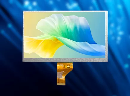
Display module: The selected tft display module receives image data and electrical supplies according to its own specification.
Backlight and touch functions: Require their own connections, power arrangements and control support.
Some host processors can drive a compatible panel directly. In that situation, a separate conversion board may be unnecessary. In other designs, a bridge or controller board is an essential part of the connection.
The matching process therefore begins by identifying the missing function, rather than selecting a board solely because its connector resembles the panel’s connector.
Use the panel manufacturer’s complete model number and current datasheet. A family name or diagonal size can cover products with different interfaces, electrical requirements and connectors.
Create a compatibility matrix before treating a board as suitable:
| Item | Panel information to obtain | Controller-board capability to confirm |
|---|---|---|
| Display interface | Exact interface type and operating arrangement | A matching panel-side output |
| Resolution | Active horizontal and vertical pixels | Support for that panel resolution |
| Timing | Pixel clock, synchronization and blanking requirements where applicable | Ability to generate the required timing |
| Data format | Color depth, packing and relevant mapping | Compatible output format and configuration |
| Electrical supply | Required rails, tolerances and sequencing | Correct supplies or a documented external arrangement |
| Connection | Connector model, pitch, contact orientation and pin assignment | A verified connector-and-cable mapping |
| Backlight | LED arrangement, current, voltage and dimming requirements | A suitable driver and control method |
| Initialization | Required commands, mode settings or configuration | Appropriate firmware and startup behavior |
Resolution is only one part of timing compatibility. Two panels with the same active pixel count may require different clock settings or blanking intervals.
STMicroelectronics’ AN4861 application note treats panel connection and LTDC clock-and-timing configuration as explicit integration tasks. The practical implication is to compare the panel’s timing requirements with the controller’s configurable capabilities.
For LVDS connections, the interface name also leaves mapping questions to resolve. Texas Instruments’ RGB-to-LVDS/OpenLDI mapping guide addresses interoperability between relevant 18-bit and 24-bit arrangements. Confirm the actual mapping supported at both ends instead of assuming that all LVDS products are interchangeable.
For each matrix row, record the supporting document and mark the item confirmed, incompatible or awaiting information. A completed list of specifications is useful only when both sides have been checked.
A connector describes a physical connection. It does not, by itself, define the signals assigned to its pins.
Two connectors may share the same pin count and pitch while carrying different power rails, data pairs or control signals. The flex cable’s exposed-contact side and insertion orientation also matter.
Check the connection in a fixed order:
Identify the exact connector at the panel.
Obtain its numbered pin assignment and contact orientation.
Compare that assignment with the controller-board documentation.
Map every required signal through the proposed cable.
Confirm that the documented cable revision matches the assembly being evaluated.
A cable should be approved as part of the panel-and-board combination. Substituting a visually similar cable can change the connection even when both ends fit mechanically.
FPC adaptation can be considered during development of a custom lcd panel, but an altered flex circuit does not automatically resolve incompatible signal standards or unsupported timing. Document the electrical function first, then confirm the mechanical connection.
Where any supply or signal assignment remains unknown, obtain clarification before powering the assembly.
Treat panel power, backlight operation and touch communication as separate checks. A lit backlight does not demonstrate that the panel is receiving a valid image, and a visible image does not demonstrate that touch input is functioning.
| Function | Information to confirm | Useful validation |
|---|---|---|
| Panel electronics | Required supply rails, tolerances, reset and power sequence | Startup, image stability and repeated power cycling |
| LED backlight | LED current, operating voltage and dimming method | Brightness control and operation at required settings |
| Touch system | Controller, communication interface, supply and software support | Coordinate alignment, orientation and intended gestures |
For the panel electronics, follow the specified startup and shutdown sequence. Identify which requirements the board handles and which remain the responsibility of the host system or external power circuit.
For the backlight, confirm the driver arrangement and the panel’s LED requirements. Texas Instruments’ backlight driver technical resources cover current, voltage and dimming considerations, reinforcing the need to evaluate this function independently of the image-data interface.
Touch integration needs a similarly explicit handoff. Establish whether the touch connection terminates at the controller board or elsewhere in the host system. Confirm the software driver and how touch coordinates will be aligned after display rotation.
During sample evaluation, include the operating states the equipment will actually use: startup, brightness adjustment, sleep and wake, and repeated power cycles. Define the environmental tests separately from a basic demonstration that an image can appear.
A matched combination is worth considering when the project needs a documented panel-and-board starting point for prototyping or system integration. It can reduce the number of separate compatibility decisions, provided the supplier confirms the configuration being supplied.
DJN’s tft controller board solution is presented as a panel-and-board combination with preconfigured initialization and adjustable display parameters. These features provide a basis for discussing the project’s integration requirements. The selected panel, board, cable and configuration should still be identified for the actual order.
Ask the supplier to document:
The panel and controller-board part numbers.
Supported host inputs and the selected panel output.
The approved cable or FPC arrangement.
Power and backlight requirements.
Firmware or configuration identification.
The functions included in the supplied assembly.
For repeat production, retain those identifiers with the sample approval record. If the panel, board or firmware changes later, the team can determine whether the approved configuration has also changed.
A matched solution is most useful when its compatibility information can be carried forward from the first sample into production.
No. A controller board has defined input, output, electrical and firmware capabilities. It may support several panels, but each combination still needs confirmation. A broad screen-size range should not be interpreted as support for every panel within that range.
No. Resolution states the active pixel count. Compatibility can also depend on the interface, timing, data mapping, electrical supplies, connector assignment and initialization settings. Use the panel’s complete model number and datasheet when requesting confirmation.
It depends on the design. Touch processing may be included in an assembly or handled through a separate controller and host connection. Ask for a connection diagram showing the display-data path and touch-data path independently, together with the required software support.
A useful controller-board inquiry contains enough information to evaluate the whole connection. Prepare the panel model and datasheet, host output, target resolution, power arrangement, backlight requirements and touch needs. Add the enclosure constraints and sample schedule where relevant.
Then request confirmation against the compatibility matrix, including the cable and firmware configuration. Retain the confirmed documents with the sample approval.
If the project does not yet have a panel selected, provide the host platform and required display behavior so the panel and controller can be evaluated together. Send those requirements to DJN’s engineering team for a project discussion.
The goal is a clearly identified, repeatable panel-and-board assembly whose functions have been checked in the intended equipment.




 English
 中文
 日本語
 한국어
 français
 Deutsch
 Español
 italiano
 русский
 Türkçe
 português
 Indonesia